Building the remote control board was a huge process that involved two different iterations. There were a lot of tiny parts that had to be had soldered with a soldering iron or heat gun. We found that it was necessary to continuously test for shorts (mostly between ground and Vcc) while we soldered on parts. First the atmega128 was soldered and check for programmability. Second the voltage regulators were added and tested. Next the max232 chip was added and db-9 connectors. A program was developed to test the function of the uart. The LCD and external SRAM shared pins so in the second board iteration when it was possible to write to the SRAM while the LCD was off a buffer had to be added so the LCD wouldn’t see any voltages while the SRAM was being written to. At one point a pin on the atmega128 was destroyed and a new pin had to be jumpered to the voltage regulator on/off pin for the LCD. After using the heat gun to put the 5mmx5mm leadless Qprox touch sensor on the board we found it had failed due to the change line wasn’t going high after touching the buttons. After some inspection it was found that there was an improper layout of a couple pins. Due to the size of the chip it was impossible to fix without making a third board. The tactile buttons that were designed as backup were used in its place.
|
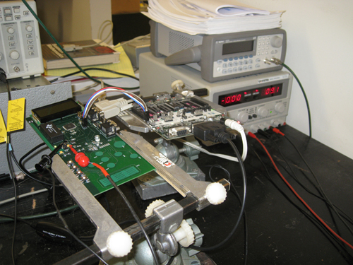
Test setup for the remote |